

DANELECTRO
Well-known member
- Joined
- Feb 24, 2003
- Messages
- 6,348
There’s been a lot of chatter and analysis of control cavity routs lately, so I thought I'd offer some information that may explain some of the specific details seen in routed features.
I've never built a guitar, nor visited the Gibson factory to see their process, but I did work in a production woodworking shop 27 years ago. I made hundreds of cutlery blocks which have knife slots routed into slabs of wood. These slabs were later laminated together to make up the completed cutlery block. The process for routing the slots would be the same as for routing guitar bodies.
Although every cutlery block was "handmade", the routs were very consistent from one to the next because they were made on an overarm pin router. This is a machine which has the router bit chucked above the workpiece in a vertical spindle. There is a large table with which to slide the workpiece under the bit. The table has a guide pin that is the same diameter as the bit and is located directly under and inline with the overhead bit. For every different configuration of cutlery block that we made, there was a specific jig that had all of the necessary rout patterns cut into the underside of the jig. The jig had locating features and clamps on the topside for the workpiece. To rout a part, you simply clamp the slab of wood into the jig, and then guide the jig into the high-speed router bit. The guide pin under the jig prevented you from routing anywhere that you weren't supposed to. It was possible to under-rout a cut if you weren't careful to keep the jig pushed against the guide pin, but you could never over-rout a slot. The pedal allows you to plunge the spindle for blind pockets.

I can say with near certainty that Gibson used a similar, if not the same machine. It is may still be in use today. Jigs would be made with guide slots on the bottom of the jig for whatever topside feature was to be routed (control cavity, pickup pockets, wire channels, etc). Each rout would require a separate jig.
For instance, routing the control cavity on a carved top Les Paul would require three routing operations with three different jigs:
- One for the coverplate rout (shown in yellow).
- One for the primary control pocket routing (shown in green)
- One for the angled routing (shown in blue). This jig would have the body slab mounted at angle to the table surface.

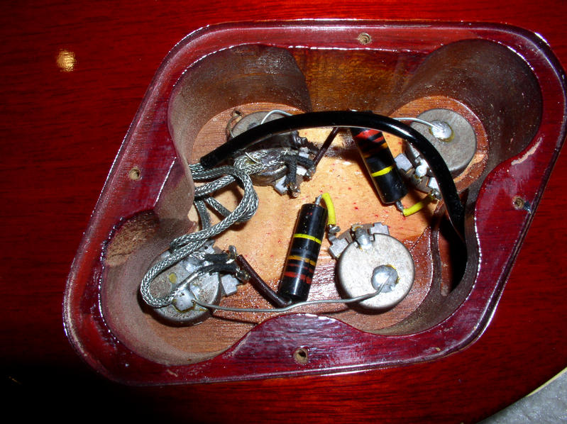
Depending on how well each of the jigs was constructed, or how accurately a guitar body slab was cut, there could be some variability between each of the rout processes. In other words, if the guitar body wasn’t located and clamped in exactly the same position between each jig, then each of the rout operations could “float” relative to each other. This explains why the flat edge between the two volume knobs varies in length, because it is the result of two different setups and operations. Same goes with the depth of the "chew marks". I believe that the reason for the rough surface of the chew marks may be because a smaller diameter router bit was used. The cutting edge of a smaller bit has a lower velocity than a larger bit, so it might have a tendency to tear at the wood. The Onsrud router had a 20,000 rpm spindle which just cut like butter. It took over 5 minutes for the spindle to wind down after shutting off the machine.
The actual profile of each rout process should be identical between all guitars manufactured, unless:
- The operator did not keep the jig pressed against the guide pin. This could allow for some edges to be under-routed.
- More than one jig existed and there were differences between them. There may have been a second jig made for backup, or one may have simply worn out and had been replaced.
The holes are drilled in separate operations (using drill jigs with guide bushings), so its possible for the holes to float relative to the routs, again depending on the accuracy with which the tooling was built. It’s likely that the drill jig for the backplate holes located itself off of the routed pocket.
Anyway, that’s my take on the control cavity routing based on my knowledge of manufacturing processes, and examining the cavities of my Historic reissues and the numerous ‘Burst cavity photos I've seen here on the Forum. I don’t have a ‘Burst to analize first hand, so if anybody would like to loan me one, I’ll be happy to look it over and maybe offer some more insight.")
- Dan
(Your Friendly Neighborhood Forensic Control Cavity Analyst)
I've never built a guitar, nor visited the Gibson factory to see their process, but I did work in a production woodworking shop 27 years ago. I made hundreds of cutlery blocks which have knife slots routed into slabs of wood. These slabs were later laminated together to make up the completed cutlery block. The process for routing the slots would be the same as for routing guitar bodies.
Although every cutlery block was "handmade", the routs were very consistent from one to the next because they were made on an overarm pin router. This is a machine which has the router bit chucked above the workpiece in a vertical spindle. There is a large table with which to slide the workpiece under the bit. The table has a guide pin that is the same diameter as the bit and is located directly under and inline with the overhead bit. For every different configuration of cutlery block that we made, there was a specific jig that had all of the necessary rout patterns cut into the underside of the jig. The jig had locating features and clamps on the topside for the workpiece. To rout a part, you simply clamp the slab of wood into the jig, and then guide the jig into the high-speed router bit. The guide pin under the jig prevented you from routing anywhere that you weren't supposed to. It was possible to under-rout a cut if you weren't careful to keep the jig pushed against the guide pin, but you could never over-rout a slot. The pedal allows you to plunge the spindle for blind pockets.
I can say with near certainty that Gibson used a similar, if not the same machine. It is may still be in use today. Jigs would be made with guide slots on the bottom of the jig for whatever topside feature was to be routed (control cavity, pickup pockets, wire channels, etc). Each rout would require a separate jig.
For instance, routing the control cavity on a carved top Les Paul would require three routing operations with three different jigs:
- One for the coverplate rout (shown in yellow).
- One for the primary control pocket routing (shown in green)
- One for the angled routing (shown in blue). This jig would have the body slab mounted at angle to the table surface.
Depending on how well each of the jigs was constructed, or how accurately a guitar body slab was cut, there could be some variability between each of the rout processes. In other words, if the guitar body wasn’t located and clamped in exactly the same position between each jig, then each of the rout operations could “float” relative to each other. This explains why the flat edge between the two volume knobs varies in length, because it is the result of two different setups and operations. Same goes with the depth of the "chew marks". I believe that the reason for the rough surface of the chew marks may be because a smaller diameter router bit was used. The cutting edge of a smaller bit has a lower velocity than a larger bit, so it might have a tendency to tear at the wood. The Onsrud router had a 20,000 rpm spindle which just cut like butter. It took over 5 minutes for the spindle to wind down after shutting off the machine.
The actual profile of each rout process should be identical between all guitars manufactured, unless:
- The operator did not keep the jig pressed against the guide pin. This could allow for some edges to be under-routed.
- More than one jig existed and there were differences between them. There may have been a second jig made for backup, or one may have simply worn out and had been replaced.
The holes are drilled in separate operations (using drill jigs with guide bushings), so its possible for the holes to float relative to the routs, again depending on the accuracy with which the tooling was built. It’s likely that the drill jig for the backplate holes located itself off of the routed pocket.
Anyway, that’s my take on the control cavity routing based on my knowledge of manufacturing processes, and examining the cavities of my Historic reissues and the numerous ‘Burst cavity photos I've seen here on the Forum. I don’t have a ‘Burst to analize first hand, so if anybody would like to loan me one, I’ll be happy to look it over and maybe offer some more insight.
- Dan
(Your Friendly Neighborhood Forensic Control Cavity Analyst)
Last edited:
")